Toll Free: 866.905.6744 | Local: 845.652.5250
Choosing the right RG11 cable is not simply a matter of selecting the thickest option on the shelf. The correct choice depends on signal distance, frequency, installation conditions, connector quality, and budget. A cable that performs well in a dry equipment room may struggle inside a hot attic or buried outdoor conduit. Small details matter. Check the conductor, shielding, jacket rating, impedance, and bending limits before purchase.
Jim Hayes, a veteran cabling educator and founder of the Fiber Optic Association, offers a useful principle: “Choose the cable for the link, not merely for its appearance.” That idea applies strongly to RG11 cable selection. A solid copper conductor may support demanding installations better than copper-clad steel. However, it can cost more and require careful handling. Quad shielding may reduce interference near electrical equipment, but it does not repair poor grounding or badly fitted connectors. That mistake is common.
This guide introduces seven practical tips for evaluating an RG11 cable before installation. We will examine signal loss, cable construction, weather resistance, connector compatibility, routing space, and long-term maintenance. You will also see why a lower-loss cable is not automatically the best solution. The thickest jacket may create problems in tight corners. The longest advertised range may depend on equipment you do not own. Real installations are rarely perfect. Even experienced installers can overlook heat, moisture, or connector quality. Measure twice. Then choose with evidence, not assumptions.
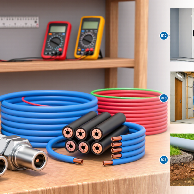
Define RG11 Cable Requirements for Your Installation
Choosing the right RG11 cable starts with the installation, not the product label. Define the signal type, operating frequency, distance, and environment before comparing specifications. RG11 commonly uses a 75-ohm design for television, satellite, broadband, and security signal systems. Confirm that impedance matches every connected device.
Measure the actual cable route carefully. Long runs can reduce signal strength, so check attenuation at your highest operating frequency. A cable that performs well at low frequencies may lose more signal above 1 GHz. Leave extra length for service loops, but avoid unnecessary coils. Too much slack can create installation problems.
Weather exposure changes the requirements. Outdoor routes need a UV-resistant jacket, sealed connections, and suitable grounding practices. For buried installation, use a cable approved for direct burial or place it inside protective conduit. Check the manufacturer’s minimum bend radius before routing around corners. Sharp bends can damage the dielectric, even when the jacket looks fine.
I once treated connector selection as a minor detail. That was a mistake. Poorly fitted connectors caused intermittent signal loss during temperature changes. Choose connectors designed for the cable diameter, then inspect the crimp or compression point. Test continuity and signal levels after installation. A sweep test is better when professional equipment is available. Recheck the plan if the cable path changes. Small assumptions often become expensive repairs.
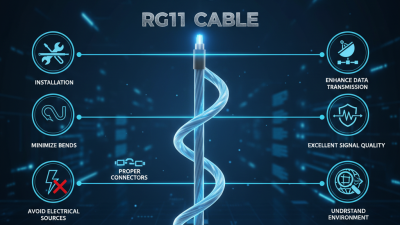
7 Tips for Choosing the Right RG11 Cable?
Start with impedance. RG11 for broadband systems normally uses 75 ohms, matching common television and data networks. A mismatch can create reflections, standing waves, and weaker reception. Check the equipment specification, not only the cable label.
Compare attenuation at the operating frequency. Published coaxial-cable test tables commonly show RG11 loss near 6–7 dB per 100 meters at 100 MHz. At 1 GHz, typical loss may reach 20–23 dB per 100 meters. These figures vary with conductor size, shielding, and temperature. CableLabs’ DOCSIS 3.1 physical-layer specification extends downstream operation to 1,218 MHz, so a cable tested only at 100 MHz may be a poor choice. Frequency matters.
Measure the actual route length. Seven checks help: impedance, attenuation, frequency range, cable length, temperature rating, connector quality, and field testing. Keep connectors short and properly compressed. A damaged connector can waste more signal than several meters of cable. I once trusted a low-loss figure without checking its test frequency. That was careless. Use a swept-frequency test when possible, following applicable IEC 61196 methods. Also review return loss, shielding performance, and bend radius. RG11 is thicker than RG6. It performs well over distance, but installation space can become a practical problem. Higher frequency is not automatically better.
Choosing the right RG11 construction starts with the operating frequency, not the cable’s outside diameter. DOCSIS 4.0 technical specifications extend downstream spectrum to 1.8 GHz. That demands stable geometry and low-loss materials. For long outdoor runs, choose a solid copper center conductor when voltage drop and signal loss matter. Copper-clad steel can reduce cost, but it may perform poorly in power-passing applications. A low-loss foam dielectric also helps preserve impedance over distance. RG11 is commonly 75 ohms, so every connector and termination must match that value.
Shielding deserves closer attention. The EN 50117 cable standard uses screening classes and measures attenuation in decibels across defined frequency bands. Higher-class designs can provide screening effectiveness around 95 dB in specified bands. That figure sounds impressive. Yet shielding fails at seams, damaged jackets, and poorly fitted connectors. A foil layer blocks high-frequency leakage, while a dense braid improves coverage and mechanical strength. Quad-shield construction may help near cellular transmitters or crowded electrical pathways, but it adds diameter and stiffness. I would not select it automatically.
Check the manufacturer’s test report against IEC 62153 measurement methods. Look for results through your actual operating range, rather than one attractive number. Maintain the recommended bend radius, keep connectors dry, and avoid crushing the dielectric. In practice, installation errors can erase carefully selected shielding performance. That part is easy to underestimate.
| No. | Selection Tip | Key Specification to Check | Recommended RG11 Construction or Shielding | Why It Matters |
|---|---|---|---|---|
| 1 | Confirm the 75-ohm impedance | Nominal impedance: 75 Ω | Choose cable specifically manufactured for 75-ohm broadband, CATV, satellite, antenna, or video systems. | Impedance mismatch can increase reflections, insertion loss, and signal standing-wave problems. |
| 2 | Select the correct center conductor | Common conductor options: solid copper or copper-clad steel | Use solid copper for lower DC resistance and power-passing applications; use copper-clad steel where mechanical strength and cost are priorities. | The conductor material affects voltage drop, powering capability, flexibility, and long-term performance. |
| 3 | Match the dielectric to the installation | Typical dielectric: solid polyethylene; outdoor designs may use moisture-resistant materials. | Choose a low-loss, moisture-resistant dielectric for long outdoor runs, ducts, or areas exposed to condensation. | The dielectric controls physical spacing and strongly influences attenuation, velocity of propagation, and moisture stability. |
| 4 | Choose the appropriate shielding level | Shield structure may include a foil plus braid, or tri-shield / quad-shield configurations. | Use dual shielding for ordinary residential environments; select tri-shield or quad-shield construction for strong RF, cellular, broadcast, or industrial interference. | More shielding layers generally improve electromagnetic interference rejection, but may increase cable diameter, stiffness, and installation effort. |
| 5 | Check frequency-specific attenuation | Review attenuation in dB per 100 ft or dB per 100 m at the actual operating frequencies. | For long runs, select a construction with lower published loss at the highest system frequency rather than comparing only the RG11 label. | Coaxial-cable loss increases with frequency and distance; the manufacturer’s test frequency and reference length must be considered. |
| 6 | Verify the jacket and safety rating | Typical choices include PVC, sunlight-resistant outdoor jackets, and plenum-rated low-smoke materials. | Use outdoor-rated cable outdoors and plenum-rated cable where local building codes require it for air-handling spaces. | The jacket protects against sunlight, moisture, abrasion, and fire-related hazards; rating requirements depend on the installation location. |
| 7 | Plan for diameter, bend radius, and connectors | RG11 is commonly about 10 mm to 11 mm in outside diameter; exact dimensions vary by construction. | Select connectors, compression tools, conduit, and supports that match the cable diameter; follow the specified minimum bend radius. | RG11 is thicker and less flexible than RG6, so unsuitable fittings or excessive bending can damage the cable and degrade return loss. |
Note: Electrical performance varies by conductor material, dielectric, shielding design, jacket, and operating frequency. Always verify the cable datasheet, applicable installation code, connector compatibility, and published attenuation values before purchase.
7 Tips for Choosing the Right RG11 Cable
Tip 1: Measure the complete route. Include vertical drops, service loops, and movement near equipment. RG11 is thicker than RG6, so extra length quickly becomes difficult to manage. Cable attenuation tables referenced by ANSI/TIA-568.4-D show that signal loss changes with frequency and distance. Do not estimate from room size alone.
Tip 2: Check the connectors before ordering. RG11 usually requires larger compression connectors designed for its diameter and dielectric size. A connector may fit mechanically but still perform poorly electrically. SCTE 40 guidance evaluates cable networks across broad radio-frequency ranges, where weak connector preparation can create reflections and unwanted signal loss. Keep each connector clean, fully seated, and properly tightened.
Tip 3: Study installation conditions. Measure conduit space, bend radius, pulling tension, moisture exposure, and temperature. IEC 61196-1 identifies these environmental factors as important for coaxial cable performance. Never force RG11 around a sharp corner. It may look undamaged, yet its internal geometry can change.
Tip 4: Compare shielding and jacket ratings. Outdoor routes need weather-resistant jackets, while indoor plenum spaces may require plenum-rated cable. Check the cable datasheet, not only the product label.
Tip 5: Leave practical service loops. A small loop supports future testing and connector replacement. Too much slack creates heavy, untidy bends.
Tip 6: Verify tools and connector compatibility. This is easy to overlook. A standard crimp tool may produce unreliable results.
Tip 7: Test after installation. Record continuity, return loss, and insertion loss where possible. A shortcut can save minutes, then cost hours during troubleshooting.
Compare cable length, connector quality, frequency range, shielding, and installation conditions before purchasing.
The chart shows representative planning values for attenuation in a 75-ohm RG11 cable over 100 feet. Actual loss depends on cable construction, temperature, connectors, and installation quality; always confirm the manufacturer’s datasheet.
Verify Quality, Compatibility, and Total Project Cost
RG11 cable can look identical on a supplier’s shelf, but internal construction matters. Check the conductor material, dielectric thickness, shield coverage, and jacket rating. Ask for a current datasheet and test report. Important measurements include impedance, attenuation, return loss, and operating temperature. A low quoted price means little if performance changes after installation.
Confirm that the cable matches your system’s 75-ohm requirements and connector type. Measure the route before ordering. Include bends, service loops, wall entries, and termination space. Check the minimum bend radius carefully. Tight turns can damage the shield or alter signal performance. The cable must also suit outdoor exposure, moisture, sunlight, or buried installation. Small details become expensive later.
Compare the complete project cost, not only the cable price. Add connectors, grounding parts, mounting hardware, tools, labor, shipping, and expected waste. A longer cable may reduce joints, but it can increase pulling effort. A cheaper jacket may create replacement costs. That trade-off deserves attention. I have seen planning estimates miss installation labor entirely. That mistake is easy to repeat. Buy from a supplier with traceable specifications, clear warranty terms, and responsive technical support. Keep batch records and inspect the cable before installation. Reject crushed sections, uneven jackets, or unclear markings. Seven checks sound simple. Skipping one can affect the whole system.