Toll Free: 866.905.6744 | Local: 845.652.5250

What Is a BMS Wire Harness and How Does It Work?

A BMS Wire Harness is the electrical link between a battery management system and the battery pack. It carries power, voltage signals, temperature readings, and balancing commands. Without this connection, the BMS cannot accurately observe or control individual cells.

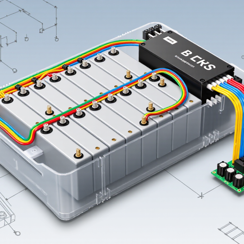
Dr. Jeff Dahn, a respected lithium-ion battery researcher, has described the battery as “the heart of the electric vehicle.” That idea explains why the harness deserves careful attention. It acts like the battery’s nervous system. Small wires connect cell-monitoring points, while larger conductors may support current sensing, grounding, or communication. A typical harness includes terminals, connectors, insulation, protective sleeving, and sometimes temperature-sensor leads. Each part must fit the pack layout precisely.

The working process is straightforward, but not simple. The harness collects cell-voltage and temperature data, then delivers those signals to the BMS. The controller evaluates the readings and may request charging, balancing, cooling, or shutdown. A loose terminal can create unstable readings. Poor routing can cause abrasion, heat damage, or unwanted electrical noise. That detail is easy to underestimate.

In practical manufacturing, technicians often check continuity, connector locking force, insulation condition, and pin order. They may also inspect the harness after vibration testing. One missed pin can affect the entire monitoring chain. Still, design assumptions are not always perfect. Real battery packs face movement, moisture, heat, and repeated service work. This guide examines how a BMS Wire Harness is built, how it operates, and which design details require closer review.

What Is a BMS Wire Harness and How Does It Work?

BMS Wire Harness: Definition, Purpose, and Core Components

A BMS wire harness is the organized wiring assembly connecting battery cells, sensors, and the battery management system. It carries cell-voltage signals, temperature readings, balancing-current paths, and communication signals. In high-voltage packs, it may also include interlock wiring and insulation monitoring circuits.

Its core components are cell-tap wires, thermistor leads, terminals, connectors, seals, protective sleeving, clips, and sometimes shielding. Each cell-tap wire measures a specific voltage point. A loose crimp or damaged insulation can create false readings, uneven balancing, or unsafe shutdowns. Small part. Large consequence.

The International Energy Agency reported over 14 million electric car sales in 2023, representing about 18% of global car sales. This growth increases demand for reliable battery wiring. A 2023 battery price survey reported an average pack price of 139 dollars per kilowatt-hour, making harness failures especially costly during service. Good design needs short signal paths, clear labeling, strain relief, and controlled bend radii. In real workshops, connector placement is often underestimated. Heat, vibration, moisture, and repeated assembly can expose weak points. Testing should include continuity, insulation resistance, terminal retention, and temperature cycling. One inspection is not enough. The harness deserves the same engineering attention as the battery cells.

How a BMS Wire Harness Connects Battery Cells and Control Units

A BMS wire harness is the electrical link between battery cells and the battery management system. It usually carries voltage-sensing wires, temperature-sensor leads, grounding paths, and communication lines. Busbars carry the main current. The harness measures each cell group.

In practical pack assembly, sensing leads attach near cell terminals or busbars. Each lead reports voltage to the control unit. Thermistor wires report local temperature changes. If one cell group rises too high, the BMS can reduce charging or disconnect the pack through contactors. Short paths matter. Extra wire length increases routing difficulty and may increase noise exposure. Connectors also need strong locking features, because vibration can create intermittent readings.

The International Energy Agency reported that global electric-vehicle battery demand exceeded 750 GWh in 2023, rising about 40% from 2022. This growth increases pressure for reliable, scalable harness designs. BloombergNEF reported an average lithium-ion battery-pack price of 139 dollars per kWh in 2023. That cost trend encourages lighter and simpler wiring, but savings should not weaken insulation or strain relief. A harness can look tidy and still fail near a sharp edge. That is an easy mistake to overlook. Careful teams check bend radius, abrasion protection, connector sealing, and cell-to-cell voltage accuracy during end-of-line testing. I would not treat the harness as a passive cable assembly. It directly affects measurement quality, fault detection, and service safety.

What Is a BMS Wire Harness and How Does It Work? - How a BMS Wire Harness Connects Battery Cells and Control Units

Data Dimension BMS Wire Harness Element Primary Function Typical Connection Point Common Electrical or Mechanical Characteristics Design and Safety Considerations
Core Purpose Battery-management-system wire harness Creates an organized electrical connection between battery cells, cell-monitoring circuits, sensors, contactors, and the BMS control unit. Battery module or pack to the BMS control board Combines low-voltage measurement, temperature-sensing, communication, and control conductors in one routed assembly. Conductors must be correctly identified and connected because a wiring error can produce inaccurate measurements or damage monitoring electronics.
Cell Voltage Measurement Cell-tap wires Carry the voltage of individual cells or groups of cells to the cell-monitoring circuit. Cell interconnects, busbars, or module terminals to cell-monitoring inputs Multiple sense wires are arranged in an ordered sequence; adjacent conductors may differ by the voltage of one cell group. Correct wire order, secure terminals, insulation, and adequate creepage and clearance are essential.
Voltage Reference Reference or negative-potential lead Provides the electrical reference used to interpret the cell-voltage measurement chain. Battery negative or the designated module reference point to the monitoring circuit Often forms the starting point of the cell-tap sequence. The reference lead should be clearly identified and protected against accidental reversal or short circuit.
Temperature Monitoring Thermistor or temperature-sensor wires Transmit temperature readings from cells, busbars, or thermal interfaces to the BMS. Temperature sensors located between or near cells to the BMS measurement inputs Usually low-current sensor circuits; resistance changes with temperature when thermistors are used. Sensors should maintain firm thermal contact without damaging cell insulation or creating pressure points.
Current Measurement Current-sensor signal wires Send measured current information to the BMS so it can estimate state of charge and detect overcurrent conditions. Shunt, Hall-effect sensor, or other current-sensing device to the BMS May include differential signal, supply, ground, or digital communication conductors depending on the sensor design. Signal conductors should be routed away from high-current switching paths where practical to reduce electrical noise.
Contactor Control Contactor coil and precharge-control wires Allow the BMS to control the connection of the battery pack to the external load and charger. BMS control circuitry to positive, negative, and precharge contactors Control circuits are separate from the high-current power path; coil voltage and current must match the contactor requirements. Precharge control helps limit inrush current into capacitive loads. Interlocks and fail-safe logic are commonly used.
Communication Communication-pair wiring Transfers measurement data, diagnostic information, commands, and status between BMS modules and a higher-level controller. Cell-monitoring unit, master BMS, vehicle controller, charger, or energy-management system Common interfaces include differential communication buses; twisted-pair construction is often used to improve noise immunity. Maintain correct polarity, termination, shielding requirements, and cable routing specified by the communication system.
Low-Voltage Power Auxiliary supply and ground wires Provide operating power and return paths for monitoring boards, sensors, relays, and communication circuits. Low-voltage battery or isolated power supply to BMS electronics Wire size is selected according to continuous current, voltage drop, temperature, and allowable insulation temperature. Protection against reverse polarity, short circuits, and overvoltage is required at the system level.
Service and Safety Interlock and service-disconnect wiring Indicates whether covers, connectors, service plugs, and other safety components are correctly closed or installed. Service disconnect, enclosure interlock, connector lock, or emergency shutdown loop to the BMS Often operates as a continuity loop that changes state when a safety device is opened. The circuit should be designed so that a broken wire or open connector produces a safe fault condition.
Connector System Multi-pin harness connectors and terminals Provide detachable, keyed, and protected interfaces between the harness and battery-management components. Cell-monitoring board, BMS controller, sensor, contactor, or module interface May include locking features, polarization, terminal seals, strain relief, and touch-safe housings. Connector ratings must cover voltage, current, temperature, vibration, environmental exposure, and mating-cycle requirements.
Mechanical Protection Insulation, conduit, tape, clips, and protective sleeving Protect conductors from abrasion, vibration, heat, moisture, and contact with conductive battery structures. Along module edges, enclosure walls, busbar areas, and connector exits Materials are selected for flexibility, temperature range, flame behavior, chemical resistance, and insulation performance. Harnesses should be secured without excessive bending, crushing, tension, or interference with cell expansion and service access.
Signal Integrity Separated and routed measurement circuits Helps preserve accurate low-level voltage, temperature, and communication signals in the presence of switching and high-current conductors. Between sensors, monitoring boards, contactors, and the central BMS Twisted pairs, short signal paths, shielding, filtering, and physical separation may be applied where required. Routing should minimize large loop areas and avoid parallel runs beside noisy power cables when possible.
Electrical Isolation Isolation barriers and isolated signal interfaces Reduce the risk of hazardous voltage reaching low-voltage control electronics or communication equipment. Between high-voltage battery circuits and low-voltage control domains Isolation may be provided by isolated power supplies, isolated transceivers, sensors, or contactor interfaces. Required isolation voltage, creepage, clearance, and insulation system depend on the pack voltage and applicable safety standard.
Wire Identification Labels, colors, numbering, and circuit documentation Supports correct assembly, inspection, troubleshooting, and service replacement. At connectors, branch points, terminals, and both ends of individual circuits Identification normally corresponds to a wiring diagram, pinout, terminal number, or circuit designation. Markings should remain legible after exposure to heat, vibration, fluids, and routine maintenance.
Testing and Validation Harness inspection and electrical test points Confirms continuity, insulation integrity, correct pin mapping, polarity, sensor response, and absence of unintended shorts. Production test fixture, connector interfaces, cell-tap points, and sensor terminals Typical checks include visual inspection, continuity testing, resistance measurement, insulation testing, and functional verification. Testing must follow the battery and BMS manufacturer’s approved procedure to avoid applying an unsuitable test voltage to electronics.
Operational Outcome Complete integrated harness assembly Enables the BMS to monitor cell voltage and temperature, estimate battery condition, control switching devices, and report faults. Throughout the battery module or complete battery pack Performance depends on accurate wiring, stable connections, suitable protection, and correct BMS configuration. A harness does not independently balance or protect cells; it provides the electrical pathways required for the BMS to perform those functions.

Signal, Power, and Safety Functions Within the Harness

What Is a BMS Wire Harness and How Does It Work?

A BMS wire harness connects battery cells with the battery management system. Its three jobs are signal transfer, power delivery, and safety control. Cell-tap wires measure individual voltages across the module. Thermistor wires report temperature from small sensors pressed against cell surfaces. These signals help the BMS detect imbalance, overheating, or abnormal voltage. Thin wires carry information. They should not be treated as ordinary cables.

Power conductors connect modules, current sensors, and switching components. They need suitable gauge, insulation, crimp quality, and strain relief. A loose terminal can create heat inside a sealed pack. That failure may remain invisible during early testing. BloombergNEF’s 2024 Battery Price Survey reported an average lithium-ion pack price of 115 dollars per kWh, increasing pressure to protect every component. Harness design is not a minor detail.

Safety circuits add another layer. High-voltage interlock loops can signal an open connector or damaged cover. Fuses limit fault energy, while shielding can reduce electrical noise in sensitive measurement lines. The harness supports these functions, but it does not make the final safety decision. The BMS does. The IEA’s Global EV Outlook 2024 recorded more than 14 million electric car sales in 2023, representing nearly 18% of global car sales. More packs mean more harness variations and more chances for assembly errors. A design may pass laboratory tests and still fail after vibration, moisture, or repeated service work. That uncomfortable possibility deserves attention.

BMS Wire Harness Design Factors and Wiring Requirements

What Is a BMS Wire Harness and How Does It Work?

A BMS wire harness connects cell taps, temperature sensors, current sensors, and control electronics. It carries precise measurement signals, not only power. The IEA’s Global EV Outlook 2024 recorded nearly 14 million electric cars sold globally in 2023. Reliable battery wiring is becoming more important. Each conductor needs clear identification, insulation, and testing before pack closure. Small errors matter.

BMS harness design starts with voltage, current, temperature, vibration, and moisture limits. Cell-tap wires should have consistent resistance, because unequal paths can distort voltage readings. Twisted or separated signal paths can reduce interference near high-current cables. Shielding may help, but incorrect grounding can create additional noise. Connector locks, seals, and strain relief must suit the battery enclosure. IEC 62619 also emphasizes safety controls for industrial lithium secondary batteries.

Wiring requirements should cover creepage, clearance, abrasion protection, bend radius, and polarity checks. A practical review verifies every pin against the BMS schematic. It then performs continuity and insulation tests. The IEA expects global electric-car sales to exceed 17 million in 2024, increasing production pressure. That is a mistake. Teams may skip rechecking. Thicker wire is not always better, and a tidy harness can hide poor service access. Document torque values, test limits, and traceability for every assembly.

Testing, Installation, and Maintenance of a BMS Wire Harness

A BMS wire harness links battery cells, voltage sensors, temperature probes, current sensors, and the control unit. Each wire carries a defined signal or power path. Correct pin mapping matters because one misplaced lead can produce false readings or damage sensitive electronics. The harness also supports balancing circuits, which help control voltage differences between cells.

Testing should begin before installation. Check continuity with a calibrated multimeter and compare every conductor with the wiring diagram. Confirm polarity, connector position, insulation condition, and terminal crimp quality. A gentle pull test can reveal weak crimps. Do not skip it. Measure resistance across relevant paths, then inspect the harness under light for cuts, crushed sections, or exposed shielding. Testing under safe, de-energized conditions is essential.

During installation, route the harness away from sharp edges, hot surfaces, moving parts, and high-current busbars. Use suitable clips and leave enough slack for vibration, but avoid loose loops. Lock each connector until its position is verified. After powering the system, compare sensor readings with an independent meter and monitor unusual temperature changes. Maintenance should include periodic checks for corrosion, abrasion, moisture, and loosened terminals. Record test results and installation changes. A perfect installation is a useful goal, not a realistic claim. Small routing mistakes can remain hidden until vibration exposes them.